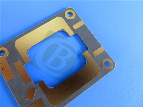
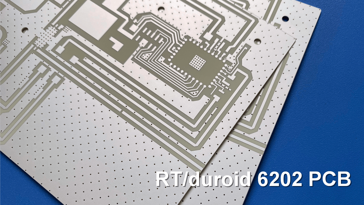
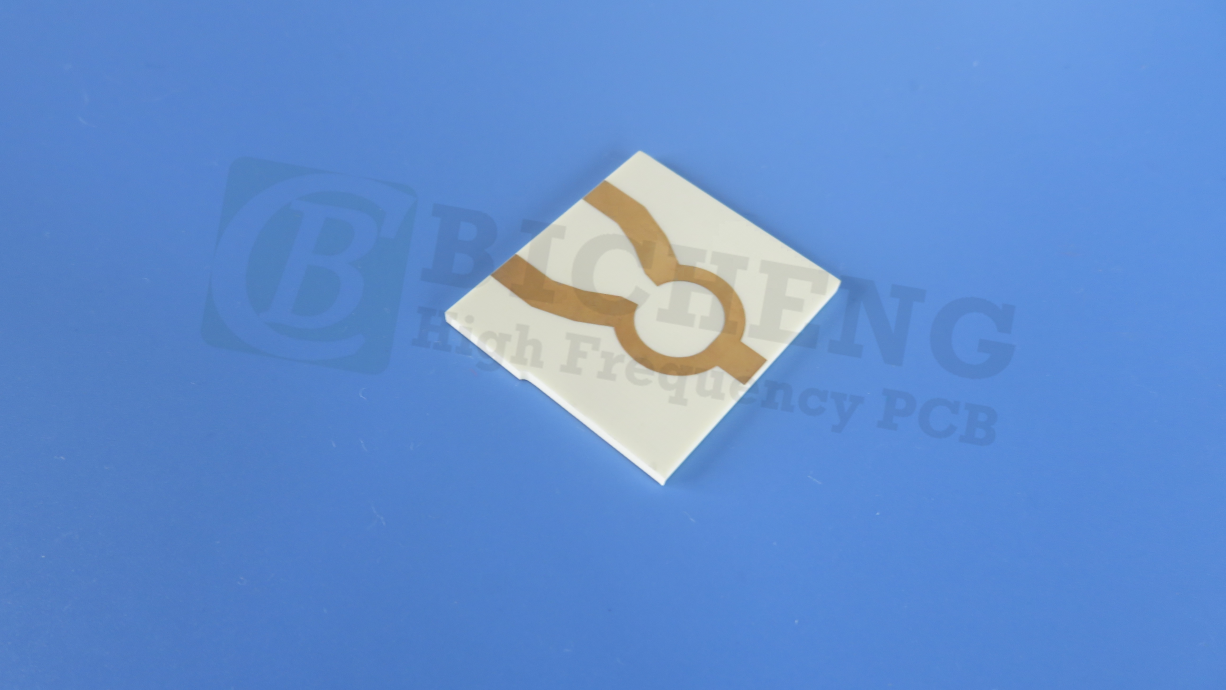
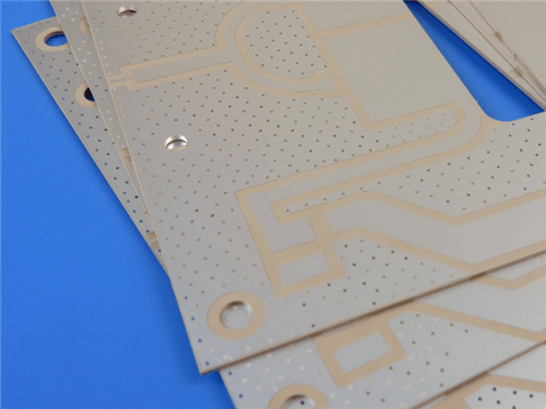
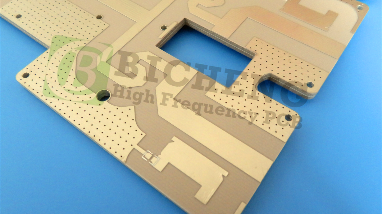
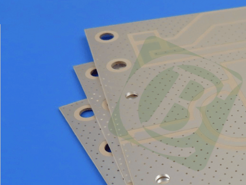
Rogers RT/duroid 6002 2-Layer 0.8mm Immersion Silver PCB – Phased Array & Radar
1.Introduction to RT/duroid 6002 PCB
Rogers RT/duroid 6002 laminates are ceramic-filled PTFE microwave materials with low dielectric constant for use in complex microwave structures. They are also low loss materials that provide excellent high frequency performance. Offering excellent mechanical and electrical properties, these materials are reliable for use in multi-layer board constructions.
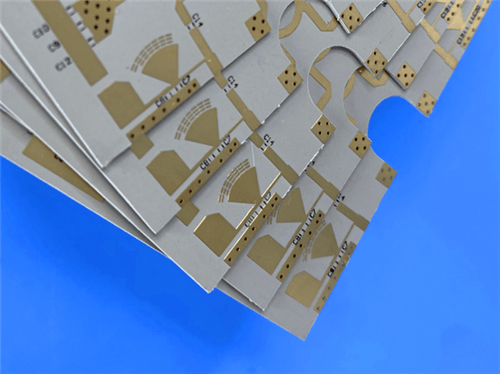
This 2-layer rigid PCB is constructed entirely with RT/duroid 6002 as the core material, providing exceptional signal integrity, thermal stability, and low-loss performance for demanding RF, microwave, and space-grade applications.
2.Key Features of Rogers RT/duroid 6002
Dielectric constant (Dk) of 2.94 +/- 0.04 Low thermal coefficient of Dk at 12 ppm/°C Dissipation factor of 0.0012 at 10GHz Td 500 °C TGA Thermal Conductivity of 0.6 W/m/k Low Z-axis coefficient of thermal expansion at 24 ppm/°C Moisture Absorption of 0.02%
3.Benefits of Rogers RT/duroid 6002 PCB
Low loss for excellent high frequency performance Tight thickness control In-plane expansion coefficient matched to copper; ideal for applications sensitive to temperature change Low out-gassing; ideal for space applications Excellent dimensional stability Excellent mechanical and electrical properties; reliable multi-layer board constructions
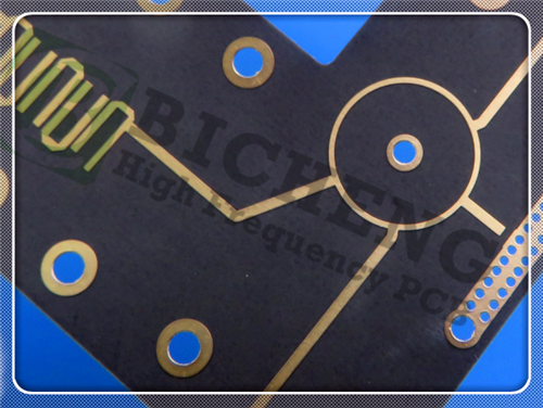
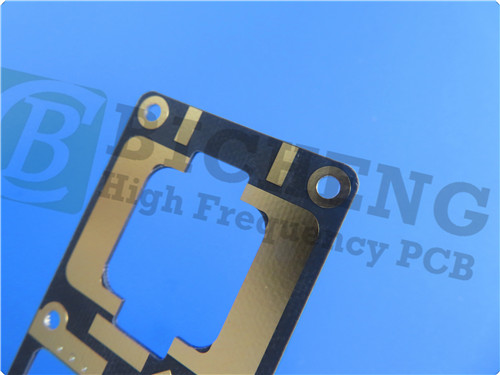
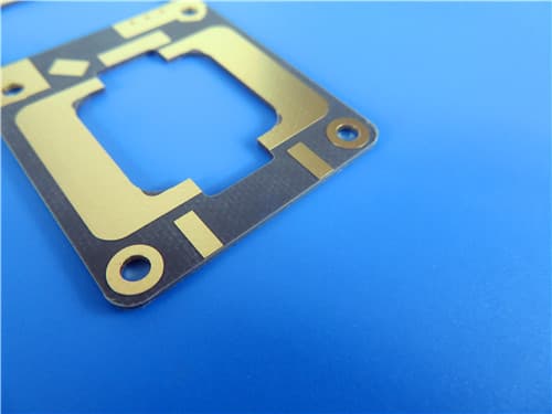
4.Rogers RT/duroid 6002 Construction Details
| Item | Specification |
|---|
| Base material | RT/duroid 6002 |
| Layer count | 2 layers |
| Board dimensions | 156mm x 87.9mm = 1PCS |
| Minimum Trace/Space | 6/7 mils |
| Minimum Hole Size | 0.3mm |
| Blind vias | No |
| Finished board thickness | 0.8mm |
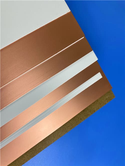
| Finished Cu weight | 1 oz (1.4 mils) outer layers |
| Via plating thickness | 20 μm |
| Surface finish | Immersion Silver |
| Top Silkscreen | No |
| Bottom Silkscreen | No |
| Top Solder Mask | No |
| Bottom Solder Mask | No |
| 100% Electrical test | Used prior to shipment |
5.PCB Stackup (2-Layer Rigid Structure)
Copper_layer_1 – 35 μm
Rogers RT/duroid 6002 Substrate – 30 mil (0.762 mm)
Copper_layer_2 – 35 μm
6.PCB Statistics
Components: 94
Total Pads: 241
Thru Hole Pads: 196
Top SMT Pads: 45
Bottom SMT Pads: 0
Vias: 126
Nets: 2
7.Primary Application Areas
Phased Array Antennas Ground Based and Airborne Radar Systems Global Positioning System Antennas Power Backplanes Commercial Airline Collision Avoidance Beam Forming Networks
8.Quality Assurance
Artwork supplied: Gerber RS-274-X
Accepted standard: IPC-Class-2
Availability: Worldwide
9.Rogers RT/duroid 6002 High-Frequency Laminate – Product Introduction
RT/duroid® 6002 microwave material was the first low loss and low dielectric constant laminate to offer superior electrical and mechanical properties essential in designing complex microwave structures which are mechanically reliable and electrically stable.
The thermal coefficient of dielectric constant is extremely low from -55°C to +150°C (-67°F to 302°F) which provides the designers of filters, oscillators and delay lines the electrical stability needed in today's demanding applications.
A low Z axis coefficient of thermal expansion (CTE) ensures excellent reliability of plated through-holes. RT/duroid 6002 materials have been successfully temperature cycled (-55°C to 125°C [-67°F to 257°F]) for over 5000 cycles without a single via failure.
Excellent dimensional stability (0.2 to 0.5 mils/inch) is achieved by matching the X and Y coefficient of expansion to copper. This often eliminates double etching to achieve tight positional tolerances.
The low tensile modulus (X,Y) greatly reduces the stress applied to solder joints and allows the expansion of the laminate to be constrained by a minimum amount of low CTE metal (6 ppm/°C), further increasing surface mount reliability.
½ oz. to 2 oz./ft² electrodeposited copper, ½ oz. to 1 oz. reverse treated electrodeposited copper or ½ oz. to 2 oz./ft² rolled copper may be specified as cladding on dielectric thicknesses from 0.005" to 0.125" (0.13 to 3.18mm). RT/duroid 6002 laminate is also available clad with aluminum, brass, or copper plates and resistive foils.
Applications particularly suited to the unique properties of RT/duroid 6002 material include flat and non-planar structures such as antennas, complex multi-layer circuits with inter-layer connections, and microwave circuits for aerospace designs in hostile environments. RT/duroid 6002 laminates have Underwriters Laboratories recognition under classification 94V-0 (Vertical Flammability Test).
10.Features and Benefits
Key Features
Dielectric constant (Dk) of 2.94 ± 0.04 Low thermal coefficient of Dk at 12 ppm/°C Dissipation factor of 0.0012 at 10GHz Td 500 °C TGA Thermal Conductivity of 0.60 W/m/K Low Z-axis CTE at 24 ppm/°C Moisture Absorption of 0.02% UL 94V-0 flammability rating Lead-free process compatible
Benefits
Low loss for excellent high frequency performance Tight thickness control In-plane expansion coefficient matched to copper; ideal for applications sensitive to temperature change Low out-gassing; ideal for space applications Excellent dimensional stability Excellent mechanical and electrical properties; reliable multi-layer board constructions Successfully temperature cycled over 5000 cycles without via failure
11.RT/duroid 6002 Data Sheet
| Property | Typical Value | Direction | Units | Conditions | Test Method |
|---|
| Dielectric Constant, εr (Process) | 2.94 ± 0.04 | Z | – | 10 GHz / 23°C | IPC-TM-650, 2.5.5.5 |
| Dielectric Constant, εr (Design) | 2.94 | – | – | 8 GHz – 40 GHz | Differential Phase Length Method |
| Dissipation Factor, tan δ | 0.0012 | Z | – | 10 GHz / 23°C | IPC-TM-650, 2.5.5.5 |
| Thermal Coefficient of εr | +12 | Z | ppm/°C | 10 GHz, 0-100°C | IPC-TM-650, 2.5.5.5 |
| Volume Resistivity | 10⁶ | Z | Mohm·cm | A | ASTM D257 |
| Surface Resistivity | 10⁷ | Z | Mohm | A | ASTM D257 |
| Tensile Modulus | 828 (120) | X,Y | MPa (kpsi) | 23°C | ASTM D638 |
| Ultimate Stress | 6.9 (1.0) | X,Y | MPa (kpsi) | 23°C | ASTM D638 |
| Ultimate Strain | 7.3 | X,Y | % | 23°C | ASTM D638 |
| Compressive Modulus | 2482 (360) | Z | MPa (kpsi) | – | ASTM D638 |
| Moisture Absorption | 0.02 | – | % | D48/50 | IPC-TM-650, 2.6.2.1 / ASTM D570 |
| Thermal Conductivity | 0.60 | – | W/m/K | 80°C | ASTM C518 |
| Coefficient of Thermal Expansion (-55 to 288°C) | 16 | X | ppm/°C | 23°C / 50% RH | IPC-TM-650 2.4.41 |
| Coefficient of Thermal Expansion (-55 to 288°C) | 16 | Y | ppm/°C | 23°C / 50% RH | IPC-TM-650 2.4.41 |
| Coefficient of Thermal Expansion (-55 to 288°C) | 24 | Z | ppm/°C | 23°C / 50% RH | IPC-TM-650 2.4.41 |
| Td | 500 | – | °C TGA | – | ASTM D3850 |
| Density | 2.1 | – | g/cm³ | – | ASTM D792 |
| Specific Heat | 0.93 (0.22) | – | J/g/K (BTU/lb/°F) | – | Calculated |
| Copper Peel Strength | 8.9 (1.6) | – | lbs/in (N/mm) | – | IPC-TM-650 2.4.8 |
| Flammability | V-0 | – | Class | – | UL94 |
| Lead-Free Process Compatible | YES | – | – | – | – |
12.Some Typical Applications
Phased Array Antennas Ground Based and Airborne Radar Systems Global Positioning System Antennas Power Backplanes Commercial Airline Collision Avoidance Beam Forming Networks Flat and non-planar antenna structures Complex multi-layer circuits with inter-layer connections Aerospace microwave circuits in hostile environments
13.Standard Thicknesses, Panel Sizes & Claddings
Standard Thicknesses (± tolerance)
| Thickness (inch) | Thickness (mm) | Tolerance |
|---|
| 0.010" | 0.252 mm | ±0.0007" |
| 0.020" | 0.508 mm | ±0.0010" |
| 0.030" | 0.762 mm | ±0.0010" |
| 0.060" | 1.524 mm | ±0.0020" |
*Additional non-standard thicknesses available from 0.005" to 0.250" in increments of 0.005"*
Standard Panel Sizes
18" × 12" (457 mm × 305 mm) 18" × 24" (457 mm × 610 mm) Additional panel sizes available
14.Standard Claddings
Electrodeposited Copper Foil:
½ oz. (18 µm) HH/HH 1 oz. (35 µm) H1/H1
Rolled Copper Foil:
½ oz. (18 µm) AH/AH 1 oz. (35 µm) A1/A1
Additional claddings such as heavy metal, resistive foil, and unclad are available
Other Available Claddings
Aluminum plates Brass plates Copper plates Resistive foils
|
.jpg)